| View previous topic :: View next topic |
| Author |
Message |
Stomper
Master

Joined: 01 Oct 2005
Posts: 473
Location: Woodburn, Oregon USA
|
 Posted: Fri Jan 18, 2008 9:14 pm Post subject: Posted: Fri Jan 18, 2008 9:14 pm Post subject: |
 |
|
| cod wrote: | huh, I calculate 108 U.S. gallons- but that can't be right, can it ?
could you pour 108 gals of milk in your tank? 
her's my math:
cylinder volume = r*r*h*Pi
19.75 is roughly inner radius, assuming .25" tank walls
= 26,945.5175 cubic inches
divide by 1728 for cubic feet= 15.593470775463
convert to US gals = 116.64
bahhh. I get different results every time!
good luck. |
I get nearly the same results as you do... (based on the outside diameter), then "eyeballing" the difference you got for the inside diameter you are right there AFAIK.
_________________
Tony Krewson
FEAR... is not my god!! |
|
| Back to top |
|
 |
drcrash
Guru

Joined: 04 Sep 2006
Posts: 705
Location: Austin, Texas
|
| Posted: Sat Jan 19, 2008 9:59 am Post subject: |
|
|
Are the given dimensions right? Is that tank almost three and a half feet in diameter? Are the dimensions reversed, maybe?
_________________
Paul (a.k.a. Dr. Crash)
Tired of buying cheap plastic crap? Now you can make your own! www.VacuumFormerPlans.com |
|
| Back to top |
|
|
ANH trooper
Master

Joined: 20 Oct 2005
Posts: 305
Location: UK
|
| Posted: Sat Jan 19, 2008 4:54 pm Post subject: |
|
|
Sorry my mistake 
It's 40" circumference and 22" tall. The width is 12" so I suppose the radius is 6".
Yeah....I'm thick  |
|
| Back to top |
|
|
drcrash
Guru
Joined: 04 Sep 2006
Posts: 705
Location: Austin, Texas
|
| Posted: Sat Jan 19, 2008 8:11 pm Post subject: |
|
|
| ANH trooper wrote: | Sorry my mistake
It's 40" circumference and 22" tall. The width is 12" so I suppose the radius is 6". |
Somebody check my math here...
A 40 inch circumference would give a diameter of 12.73; I'm guessing that's a better measurement than the 12 inches?
Assuming something in between, and allowing for a bit of thickness to give the inside diameter, call it 6.25.
The cross-sectional area of the circular way is pi times 6.25 squared, or about 3.142 x 39, or about 122.54 square inches. Multiply that by 22 to get about 2696 cubic inches.
2696 cubic inches divided by 1728 (cubic inches per cubic foot) is about 1.56 cubic foot, which is 11.67 U.S. gallons.
Minus a little for the roundedness of the end domes (?), I'd say that's about an 11 gallon tank.
_________________
Paul (a.k.a. Dr. Crash)
Tired of buying cheap plastic crap? Now you can make your own! www.VacuumFormerPlans.com |
|
| Back to top |
|
|
ANH trooper
Master
Joined: 20 Oct 2005
Posts: 305
Location: UK
|
| Posted: Sun Jan 20, 2008 7:29 am Post subject: |
|
|
Cool thanks Dr 
What do you reckon about the size of the tanks? Will one be enough for a 24" x 24" platen or would you use two? |
|
| Back to top |
|
|
ANH trooper
Master
Joined: 20 Oct 2005
Posts: 305
Location: UK
|
| Posted: Sun Jan 20, 2008 10:02 am Post subject: |
|
|
Take a look at this diagram and let me know what you think.
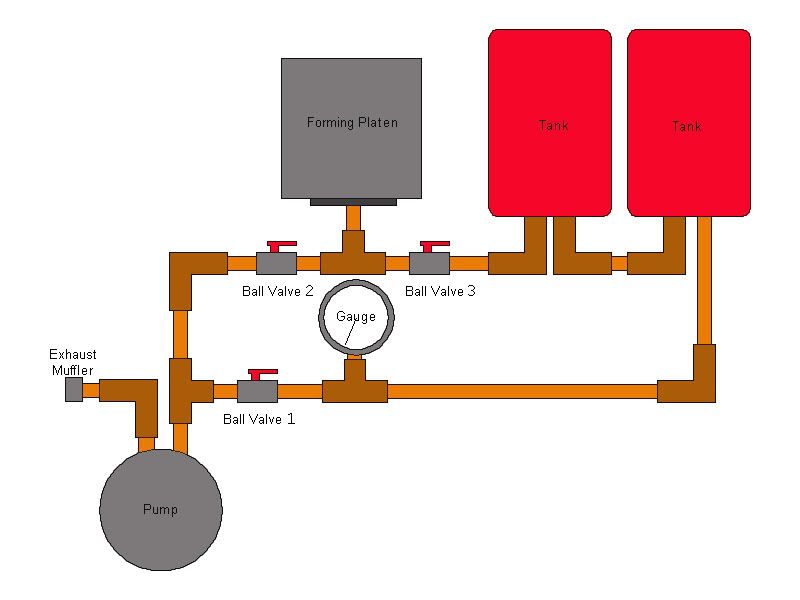
Valves 2 and 3 are closed while a vacuum is being pulled and then valve 1 is closed to hold the vacuum in the tanks. Valve 3 is then opened once the heated plastic hits the platen to suck down the plastic. Valve 3 is then shut and valve 2 opened to allow the vacuum pump to keep pulling until the plastic has cooled.
Valves 2 and 3 will be up near the platen and valve 1 will be down below out of the way and will not be used in the forming process, only to hold the vacuum in the tanks.
I am not competely sure if the tanks have to be shut off while the vacuum pumps keeps the pressure applied to the plastic, but I would imagine it would so there is less air to be removed.
I just want to know what you guys think before I plumb this lot up. |
|
| Back to top |
|
|
Stomper
Master
Joined: 01 Oct 2005
Posts: 473
Location: Woodburn, Oregon USA
|
| Posted: Sun Jan 20, 2008 10:48 am Post subject: |
|
|
IMO you have too many valves to fiddle around with.
1.
Delete the separate circuit that valve-1 is on
2.
Put valve-2 on the outlet of the tee going to the platen. (between the platen and the tee)
3.
Place the vac-gauge where valve-2 currently is.
You now will have a two-handed valve assembly that you have a better chance of operating "simultaneously" instead of in "stages", which could pose problems when you have hot plastic that is solidifying quickly. When I get around to building my machine, I'm going to use a 3-way valve for 2-stage operation.
_________________
Tony Krewson
FEAR... is not my god!! |
|
| Back to top |
|
|
drcrash
Guru
Joined: 04 Sep 2006
Posts: 705
Location: Austin, Texas
|
| Posted: Sun Jan 20, 2008 11:40 am Post subject: |
|
|
Check out the second diagram in the first posting in this thread over on CNCzone:
http://cnczone.com/forums/showthread.php?t=38493
(That's linked from my www.vacuumformerplans.com site, BTW.)
If your vacuum pump can keep ahead of leakage around the edge of the platen, one medium-small tank will work fine. (I think an 11 gallon tank should be fine for a 2 x 2 foot machine.) You only use the tank for the initial pulldown, then close it off and use the vacuum pump alone for the long hard pull.
The initial pulldown will pollute your tank, but when you close it off, the pump will pull a higher vacuum, limited by the ratio of the leakage rate to the pumping rate. When you're finished, you close the valve to the platen and open the valve to the tank to re-evacuate the tank.
_________________
Paul (a.k.a. Dr. Crash)
Tired of buying cheap plastic crap? Now you can make your own! www.VacuumFormerPlans.com |
|
| Back to top |
|
|
ANH trooper
Master
Joined: 20 Oct 2005
Posts: 305
Location: UK
|
| Posted: Sun Jan 20, 2008 2:37 pm Post subject: |
|
|
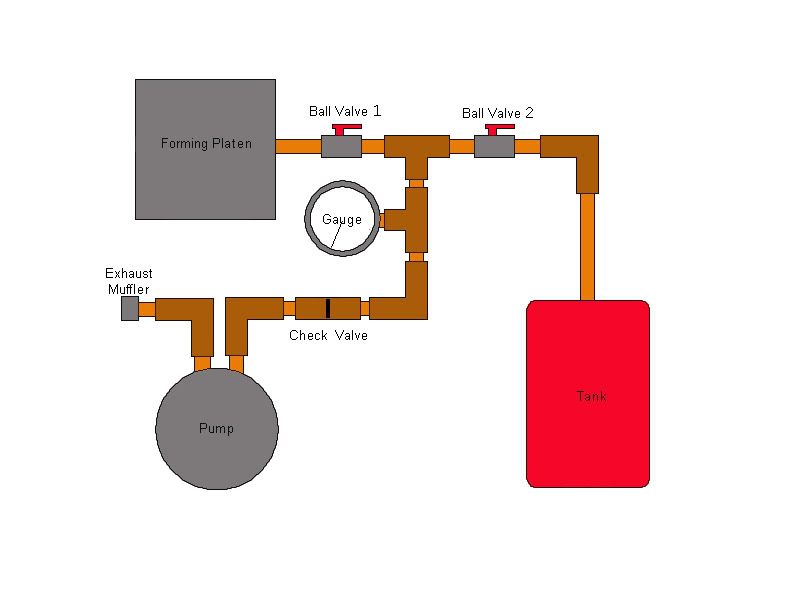
Thanks for the input!
I've taken your advice and altered the design. How's this?
 |
|
| Back to top |
|
|
Stomper
Master
Joined: 01 Oct 2005
Posts: 473
Location: Woodburn, Oregon USA
|
| Posted: Sun Jan 20, 2008 4:25 pm Post subject: |
|
|
Looks perfect, and it is the same (schematically) as the one Dr. Crash referred to in his post.
_________________
Tony Krewson
FEAR... is not my god!! |
|
| Back to top |
|
|
ahillworks
Master

Joined: 18 Nov 2007
Posts: 308
Location: Orlando FL
|
| Posted: Mon Jan 21, 2008 5:51 pm Post subject: |
|
|
| Now that we see this I wounder if my design is ok. I see there are two valves. I have just one. Whats the major difference. I have exta pipe i can always change what I have to make things better if needed. I just want some one to explain why having the two would make a differ. |
|
| Back to top |
|
|
Stomper
Master
Joined: 01 Oct 2005
Posts: 473
Location: Woodburn, Oregon USA
|
| Posted: Mon Jan 21, 2008 7:16 pm Post subject: |
|
|
The pictures above illustrate a two-stage vacuum system.
When you open the valve to your tanks to make a pull, you are pulling air into them and this decreases your "vacuum power" as the tanks refill, so what you do is shut that valve to your tanks after the plastic has formed to your molds from the vacuum in the tanks, while leaving the other open to the platen so that the vacuum pump will pull against the seal of the plastic & the platen. This is a better arrangement because the vacuum level will increase faster as the volume of air is much smaller than the tanks... providing you don't have massive leaks between your platen surface & the plastic sheet. You can have much tighter pulls against your molds, and get away with using a smaller vacuum reservoir (tanks).
_________________
Tony Krewson
FEAR... is not my god!! |
|
| Back to top |
|
|
ahillworks
Master
Joined: 18 Nov 2007
Posts: 308
Location: Orlando FL
|
| Posted: Tue Jan 22, 2008 1:39 pm Post subject: |
|
|
| Got it will change this when i get home I already have all the piping and a ball valve. Knew I had extra for a reason =). See I would wasted money on PETG this week and wasted more time with less results. I knew I waited for a reason. |
|
| Back to top |
|
|
ANH trooper
Master
Joined: 20 Oct 2005
Posts: 305
Location: UK
|
| Posted: Wed Jan 23, 2008 2:26 pm Post subject: |
|
|
Here's a couple pics of my machine so far.
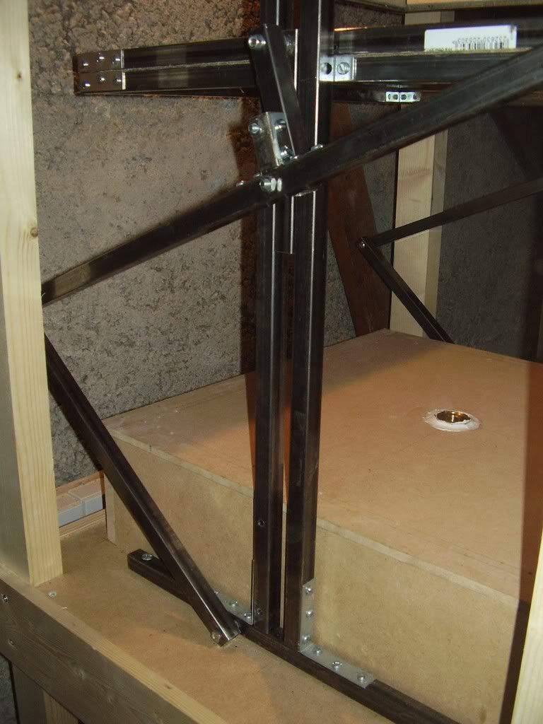
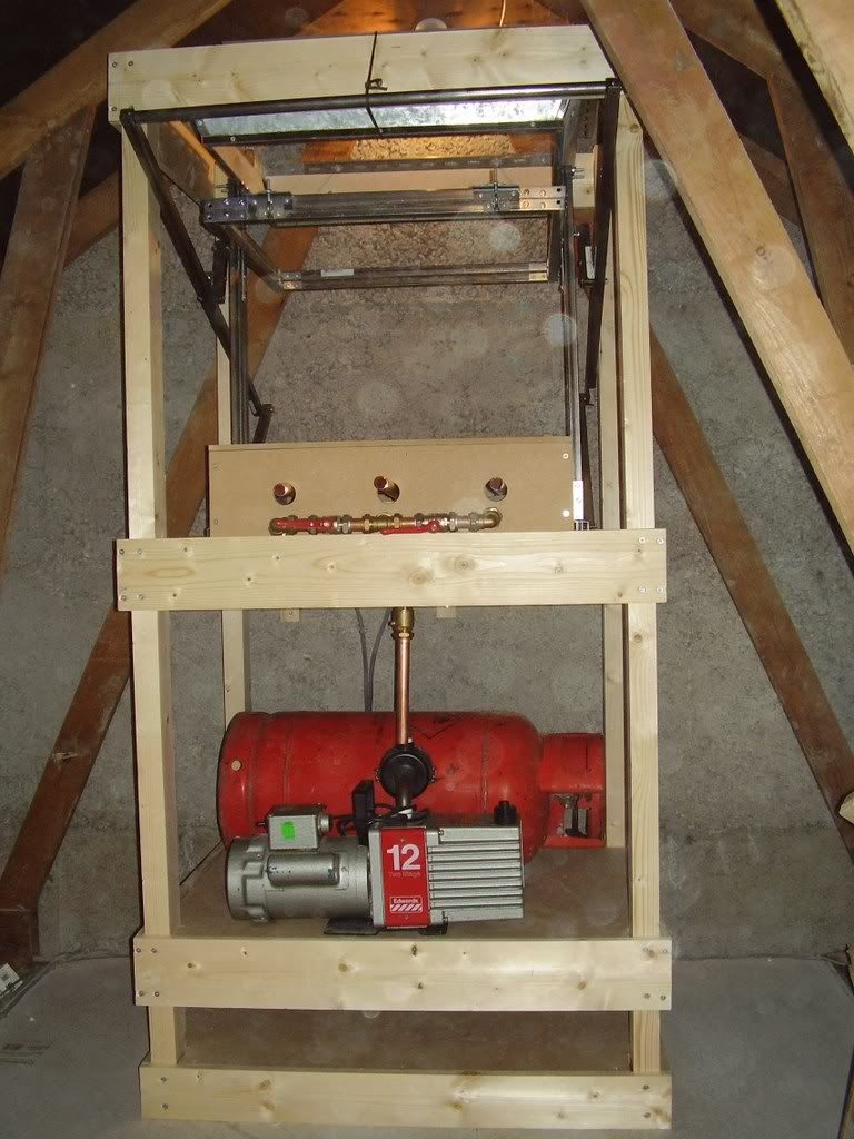
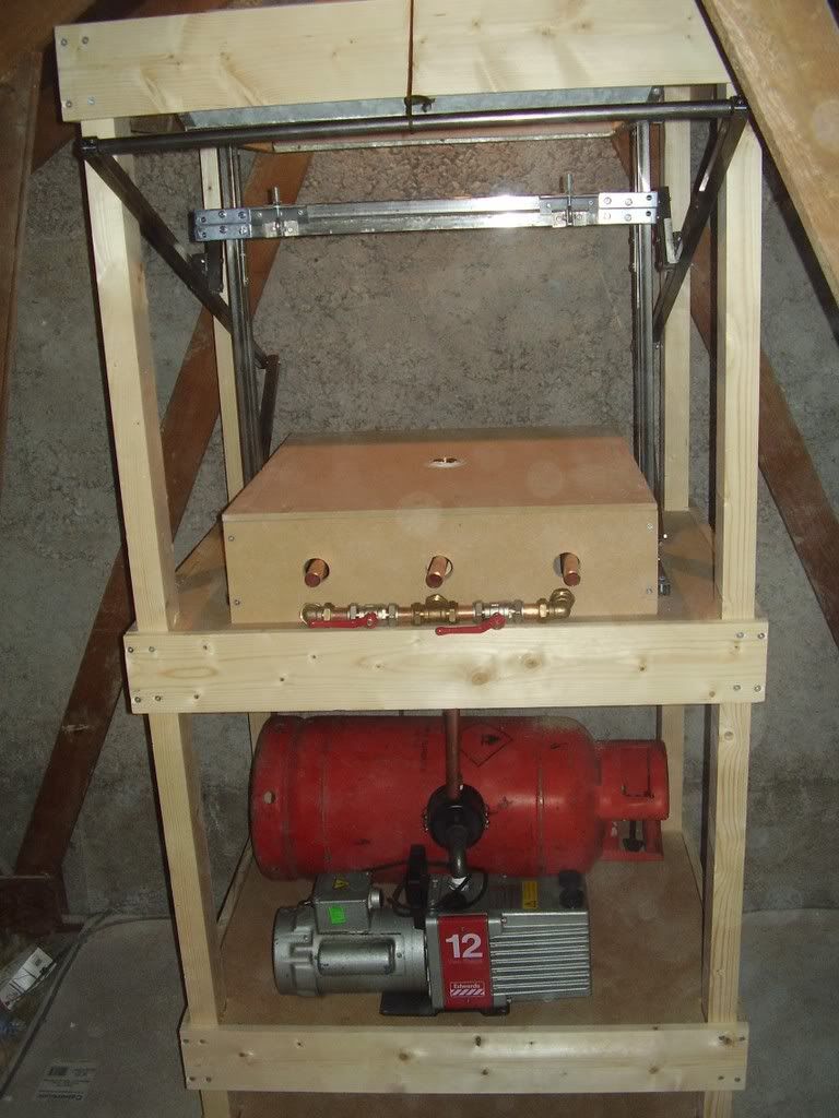
I added the bottom shelf to store my plastic. The lifting mechanism is working, but still need to fine tune it and figure out the best way of keeping it in the upright position.
I need to get the vacuum tank modified to accept my plumbing. I thought it would be too easy to use the regulator on the bottle
My coil wire has arrived and I am using Supalux heat resistant fire board for the backing. I beleive this is the same stuff TJ uses. I haven't even marked out the spiral yet, but I do have all the cotter pins as I am going to make it like Dr.Crashs' design. |
|
| Back to top |
|
|
ahillworks
Master
Joined: 18 Nov 2007
Posts: 308
Location: Orlando FL
|
| Posted: Wed Jan 23, 2008 4:25 pm Post subject: |
|
|
| I love it but how did you do the pipping? I am trying to figur it out. I had to re do my pipes the other day. |
|
| Back to top |
|
|
|