|
CONTENTS:
TK560 Main
Communicators
Phasers
Tricorders
Helmets
Blasters
Stormtrooper Armor
Lightsabers
Astro-Mech Droids
How-to Guides
Vacuform Table
Cylon
Centurion
Viper Pilot Helmet
M41-a Pulse Rifle
Motion Tracker
B5 PPG
Retro
Box Designs
Repair/Restoration
Replica Parts
40th Anniversary
Replica
Weapons/Gear
Reenactment Units
ME262 Project
Civilian
Marksmanship Program |
M1
Garand Rifle
M1903 Springfield
Rifle
M1 Carbine
Discussion
Board
Lauren Photo Albums
Egner II
Design
Please
note, that the images, logos, and respected artworks, are property of
the original copyright owners. TK560 has no affiliation with any of the
intellectural property owners. This is a fan site dealing with movie and
television replica props, original GIjOE action figures, World War II
memorbilla, and marksmanship/ firearms interests. Most of the images used
on this site are photgraphed by the site owners. Official logos are used
to identify specific products/ manufacturers.
|
Build
Your Own Vacuum Form Machine
Make
your own vac-u-form machine in your garage from simple hardware store
items, here's how
Vacuum
Forming Machine Project: Thurston James' Design |
|
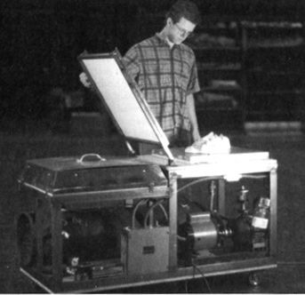
Thurston
James's Vacuform machine from The Prop Builder's Molding
and Casting Handbook, page 175. |
The OriginaI design:
This
is the Thurston James' vacuum forming machine from his book The
Prop Builder's Molding and Casting Handbook, page
175. This is a great book and I have most of Thurston James' books.
Get them at Amazon.com
today, if you don't have it already. His design is discussed in
detail, but not to the extent that I could just sit down with the
book and build his table. Its not a building guide. There is enough
concept and general information to get started, however, and with
a little time and effort, reverse-engineering and researching, this
project has finally taken off. There are no plans, or building diagrams
in his book, except for a wiring diagram for the oven. The rest
of this project has to be "re-imagined".
A lot
of vacuformers will tell you to just use pegboard, and a shop vac.
This does work pretty well. The only downsize is the pegboard has
to be supported, and does have a tendency to sag under the weight
of a large mold. The shop vac can deliver surprising results with
thinner materials. But for a detailed pull on a larger machine,
I wanted to follow as close as possible to what Thurston James describes.
Besides this is a re-examined "practical" and cheap replica
of his famous table. The following is my documentary on the production
of this table. |
| 
Click
on the image for a larger view.
Still a work in progress, but it does work!
Note,
vacuum forming, accustom,'vac-u-form', vac-forming and thermoform
are interchangeable terms. |
This
project consists of several "modules" that should be built
in sequence. Here is an outline:
Module
1 - Forming surface: this is the section that will get
the most "wear and tear" and is the easiest to build with
common tools and materials. DONE
Module
2 - Holding Frames: 3/4" steel tubing MiG welded.
Hinges and clamping assembly are added. Alternate materials could
also be used, including aluminum square-tubing, or even 1x1 pine.
DONE
Module
3 - Forming Cart: This is made of 2x4's and a 24"
square sheet of MDF. I added caster to the side so it will be easy
to move this around the shop. DONE
Considering how much space this machine takes up, I'm considering
making my machine a "table-top" version; no cart!
Module
4 - The Oven: made from a 3'x5' sheet of 1/2" Hardibacker
500* concrete backer board, a length of precoilled Nichrome wire
#22, and some 60 ceramic posts. External shielding is made from
the Hardibacker 500, an angle iron 1" base is also made to
hold the whole thing together. An electrical box with wire and a
switch. The oven works! DONE
Module
5 - Oven Cart: Like the forming cart, this is made of 2x4's
and a 24" square sheet of MDF. DONE
Again, I need more space in my shop, so its off to design a table-top
box for my machine.
Module
6 - Vacuum System: UPDATE:
My first successfully pull using the machine was done with a 3hp
shop vac. It works pretty well. I'm thinking of using a sump pump
check valve rigged with a self closing spring, and a tank with a
fair amount of vacuum. The two vac sources working together should
give me the most practical and useable approach. Another option
for more vacuum could be to use 2 shop-vacs in sequence to generate
more inches of Hg. I think one of these two solutions will solve
most of the vacuum issues, and eliminate the need for the more complicated
tank and pump and plumbing system. We'll see.
The
pump/tank option uses a GAST 1065 pump, and a 30gallon slim hot
water tank, two one quarter turn 3/4 inch valves, and some 3/4 inch
pipe fittings. IN PROGRESS
The
availability of the parts is what determines the construction sequence
for me. I went with the forming surface, then the holding frames,
then the forming cart, then the oven, oven cart, then the vacuum
system.
*It has come to my attention that, over time, the high heat from the nichrome wires will cause the Hardibacker 500 to fatigue, and eventually crack. This could pose a potential fire hazard. Currently a replacement calcium silicate fiberboard is being researched. I got 3 years of regular use from my machine build with the Hardibacker 500, but anyone considering this material should understand it's limits. Consider it a less than ideal substitute. |
MODULE
1 - The building process begins: Vacuform Machine Forming side |
 |
 |
 |
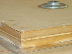
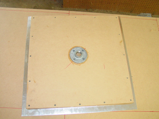
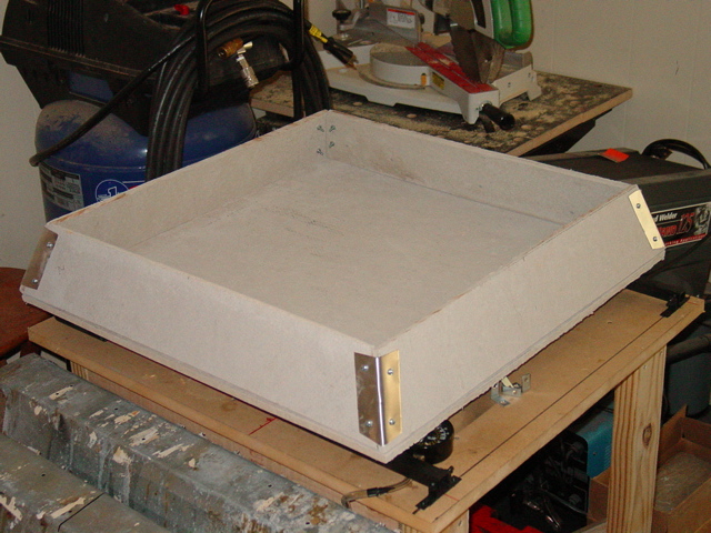
| Here
a look at the innards of the forming surface.
Note, I used 3/4" MDF for the top and bottom and scrap
1/8" plywood for the "sandwich". I then silicone
caulked the whole thing together. Make the MDF 21.5"
square. |
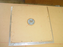
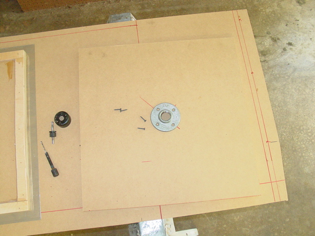
Here I
am centering the floor flange. I used a 1" floor flange
so that I could hook up my shop-vac right to it. For the hi-vac
parts, most of the plumbing will be 3/4". |
This is
a shot of the sandwich screwed together. I have positioned my
aluminum sheet metal evenly under the forming sandwich. |
 |
 |
 |
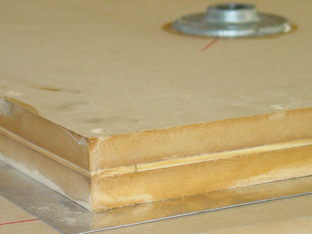
| Here is
a view of the sandwich. Its clamped to the work bench, and I
just use my hands to bend the aluminum sheet metal to the sides.
A snip at the corners and some light tapping with a mallet and
I'm done. Its ready to seal with adhesive-backed aluminum tape.
I used a 1/2" brads to mount the sheet metal to the MDF. |
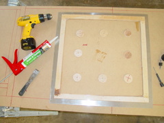
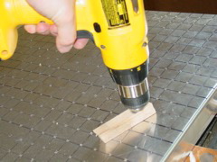
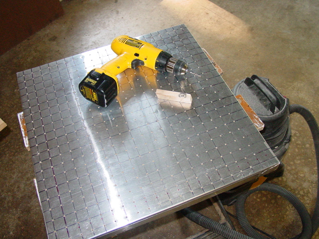
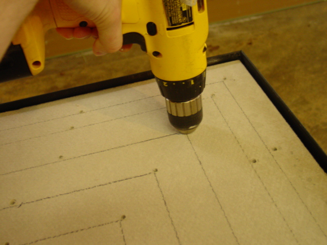
Starting
from the center I drew a 1" square grid pattern. Then using
the block of wood as a depth guide, I drilled the 1/8"
holes. Lots of holes... 484 or there abouts. I could have used
a box made of 1x4s and pegboard, like my other tables. But... |
Forming
surface finished! Now, onto the holding frame. I already know
the scale of the frame, I'm just avoiding having to break out
the welding machine. Normally, the holding frame would have
been made first. I found this relatively easy, skill level II. |
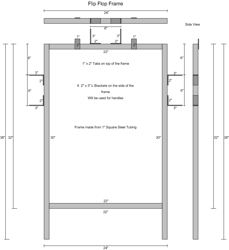
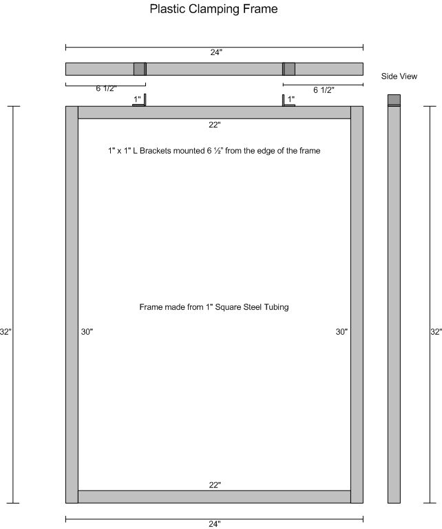
| MODULE
2 - The holding frames |
 |
|
|
| Laying
out the Holding Frame: Using 3/4" square
metal tubing, I wanted the outside edge of the frame to be 24".
Measure and cut the metal tubes. I made the bottom one with
5" extensions. Two at 24", two at 29", and four
at 22.5". Try to be precise and make clean cuts. Grind
down any extra metal and be sure the corners where the edges
meet are plumb and flush. |
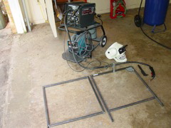
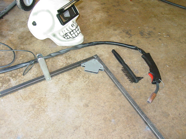
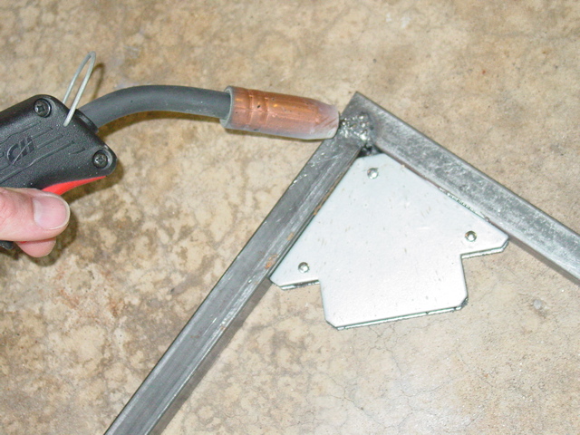
MiG
weld that baby together. I used a magnetic welders guide to
get the frame square. I worked on the floor mainly because
I don't have a fire proof work surface. Please don't laugh
at my poor welding technique. Its been 20 years since I last
welded something! I really like MiG welding, and if done properly
it should hold up fine. Just be sure to get a good "bead".
and, yes that my welders helmet. |
Here
is a shot of the welders guide and the final weld.This process
took more time to cut the tubes than to weld together. MiG
welding is pretty easy, once you get the hang of it. Practice
welding on some scrap first. This could have been pop-rivited
together with pieces of metal straps, or brazed or stick welded.
Heck, I could have made these from sturdy 1x1s and L brackets
or aluminum tubes. |
 |
|
|
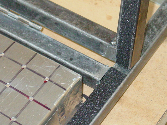
| If you
did all the work correctly, there should be a 1/2" or so
space between the forming surface and the inside of the metal
frame. It would look something like this. Make sure the corners
of the forming surface has no sharp edges. Otherwise, it might
tear the hot plastic and loose vacuum. |
I
found in my parts bin a bunch of these metal brackets. So
I used them for the frame mount. The bolt is a 1/4" with
a wing nut. I think these came from one of those toilet tank
repair kits. I cut the bolt down to be just longer than the
wing nut. |
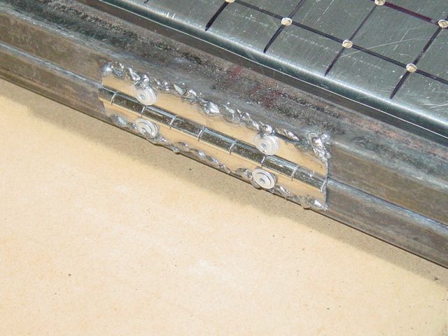
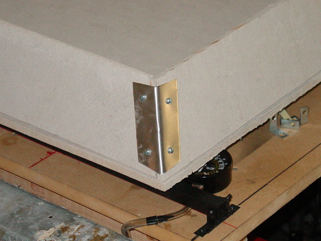
Here
is some scrap "piano" hinge I cut down, and pop
riveted it to the frame. I then MiG welded it to the frame.
That chrome plating on the hinge sucks, so does my welding... |
 |
|
|
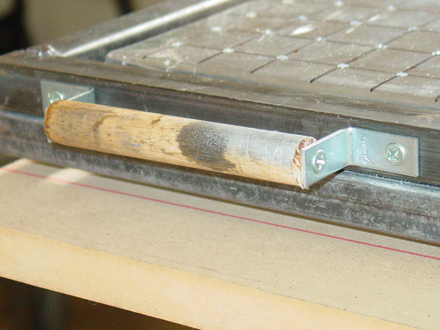
| More of
those little metal brackets I used earlier for the holding frame
hinge, now I'm using them to make some handles .A wooden dowel
rod screwed into the holding handle. I need to make three. One
on each end of the frame. |
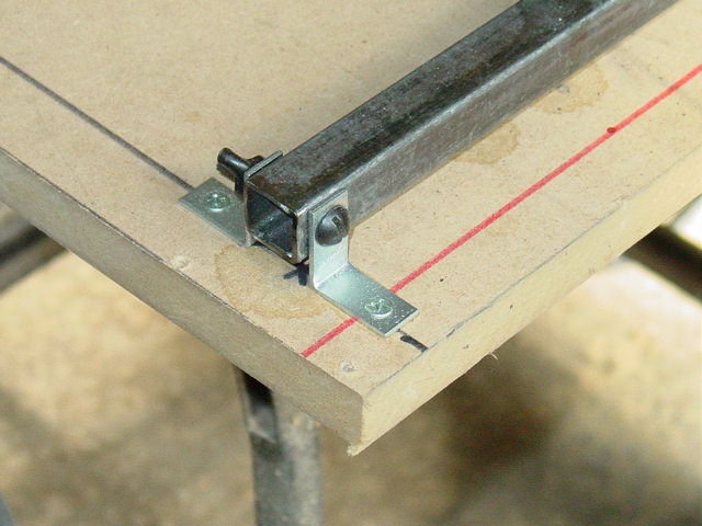
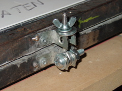
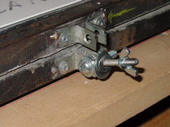
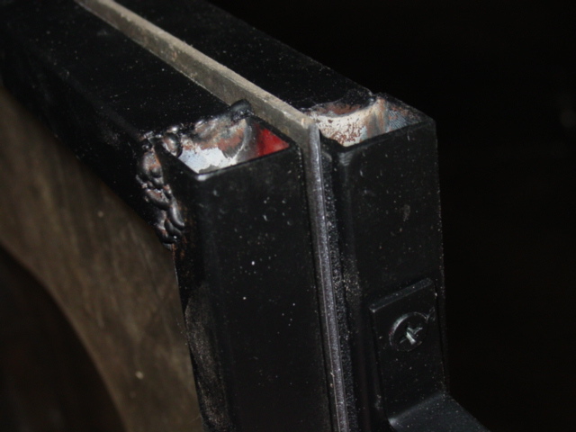
The
clamping fixture is a wing nut, a long eye bolt and 4 'L' brackets mounted as shown. The receiving end gets the corners ground down a bit to make it easy to tighten down. The originals bent bolts just did not hold up.
UPDATE: Jan. 2007
|
Here
is another view of the clamping fixture. Works like a charm!
These are pop riveted and tack welded in place. Each part is easy to replace if there is an issue.
UPDATE: Jan. 2007
|
 |
|
|
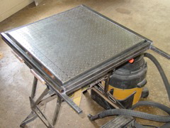
| I then
cut a sheet of MDF to the proper dimensions and bolted the frame
assembly and forming surface down. Underneath, I cut a hole
for the floor flange to poke through. This is all there is to
the forming side of the vac-machine. If I scrap the complex
vac-system, this becomes pretty portable. |
Inside
the frame I used some of that non skid surface tape. 3M makes
the stuff for ladders and steps, and its self adhesive. I'll
see if it can take the heat. If not, I'll epoxy some sand
on it! the first test pull seems to indicate this will hold
up fine. But over time, I don't know. |
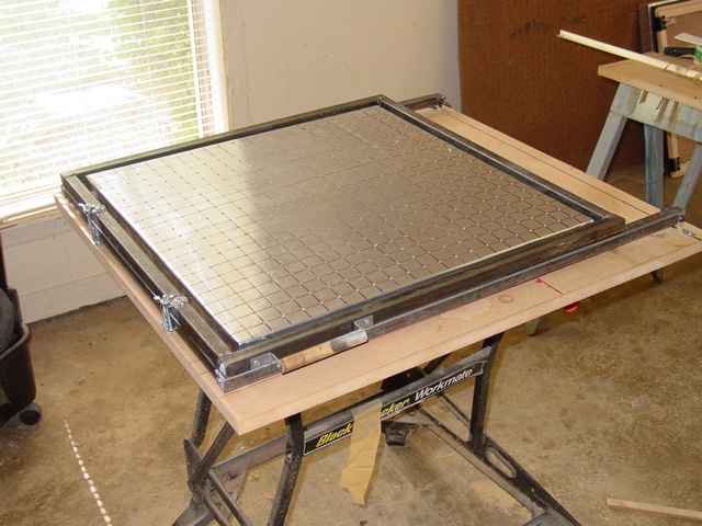
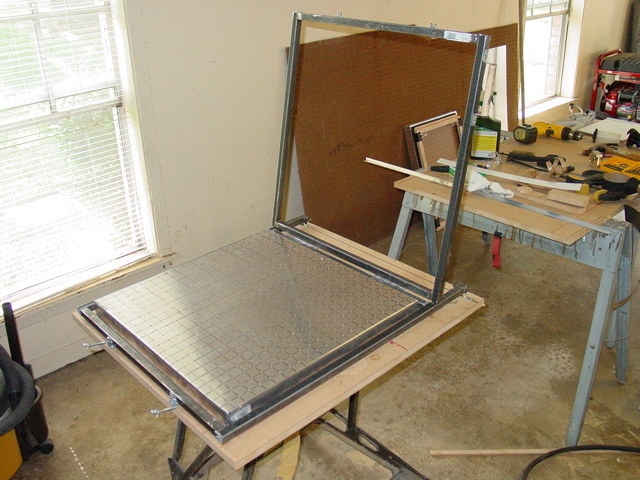
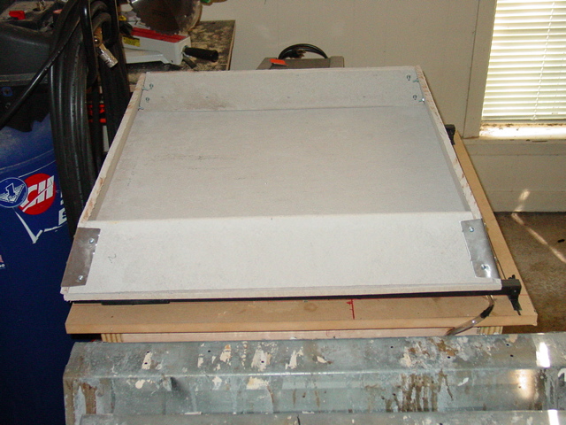
Here
is a view of the forming surface with the frame in the open
position for removal and installation of Styrene sheets. Really
easy way to do this step. Much better than my old machines. |
| MODULE
3 - The forming cart |
 |
|
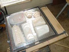
|
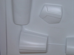
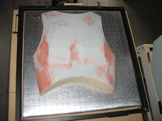
| Test fitting
some of the stormtrooper armor parts. If I can pull this much
at at time, that would be nice! The frame will be painted to
prevent rust and to look pretty. Now its off to building
the cart. |
Thurston
James made his from square metal tubing, but said a 2x4 fir
would work just as well. I wanted to keep the vacuform machine
small enough to move around, so instead of making it on one
big "cart" I'm putting the forming surface on one
small cart, and the oven on another. We'll see how this works.
If I ditch the complex hi-vac system, I can scrap the carts
all together, and build it as a table top unit. |
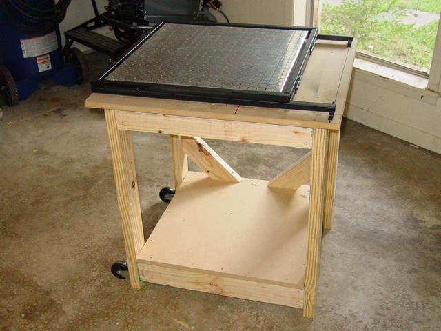
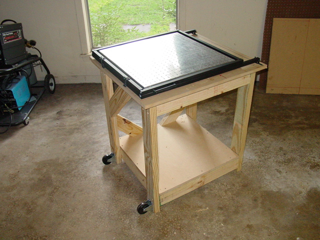
The
forming cart will attach to the oven cart to make one large
vacuum table. I made the cart from 2"x4" studs.
The inside dimensions are 24"x24". Height is 30"
to the base. The same height as my Workmate. I put casters
on the side so I can tip it over and roll it around the shop.
At this point the forming side is complete. All that is left
to do here is solve the vacuum issues. |
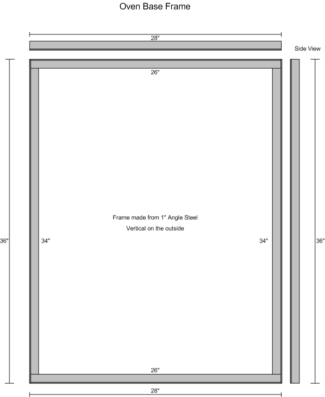
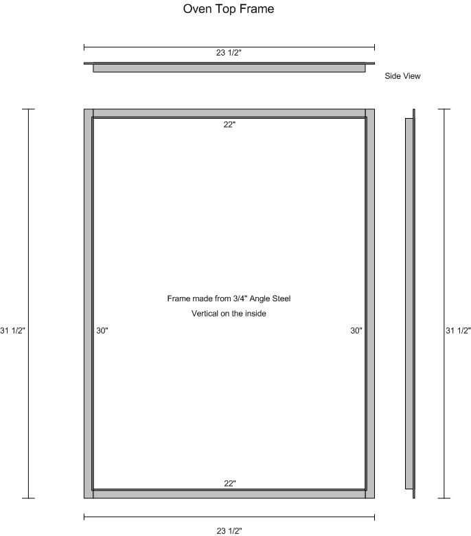
| MODULE
4 - The Vacuform Machine's Oven |
 |
|
|
| Here is
a shot of the Hardibacker 500 cementbaord material I'm using
as the oven walls and floor. Basically cut a 28" square
of the stuff, and then make four 28x 4.5" strips. To get
the taper sides, you just measure from the center out to 24"
and mark. The sides are then cut at an angle and you have the
trapezoid. |
This
is a detail of how I attached the sides. Its a strip of aluminum
with holes drilled and short screws holding it all together.
Cut two of the sides 1" shorter, this allows for the
thickness of the Hardibacker material. Finally to hold the
sides together, I too some scrap aluminum sheet metal, and
folded, trimmed it to fit, and screwed it to the sides. |
The
oven is sitting on the forming surface. The scale worked out
fine from the book. I'll add a reinforcing walls, and a metal
base soon. The walls will be made from the roof flashing material
and painted black. Skill level II, but you will need a power
saw to cut the concrete board. |
 |
|
|
| After welding
a 1" angle iron material to form a sturdy base frame, I
began drilling the holes for the post mounting screws. Off set
all but the tapping posts 1/2 inch from the wire guide lines.
use a masonry bit that is slightly larger than the #10 screw. |
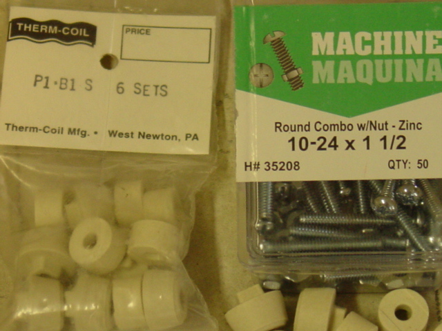
Here
are the ceramic posts and mounting screws. I used 2"
#10-24TPI for the terminal posts and a top mounted wing nut... |
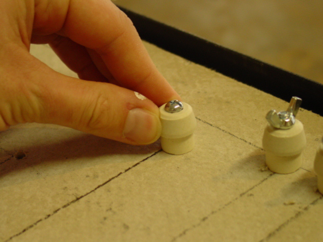
Some
test fitting.. Regular ceramic post and terminal post [the
one with the wing nut] |
 |
|
|
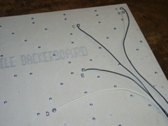
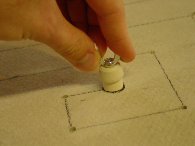
| Starting
from the center... Mount the screws. The underside of the backerboard
might need some scraping, as the holes drilled through are rough
on the underside. |
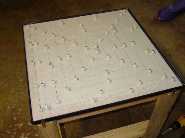
And
this is what mine looked like after drilling and mounting
all the ceramic posts and terminal posts. Note the metal frame,
and the cart! |
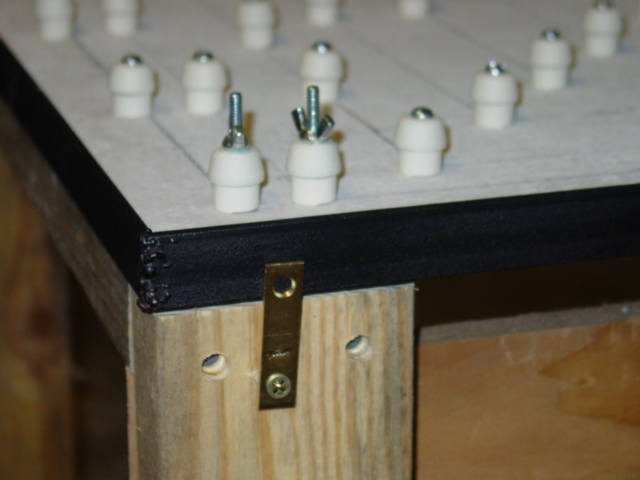
Here
is a detail shot of the way I mounted the oven frame to the
cart. I'm thinking of reworking the carts to convert this
to a table top machine. Storing this contraption is getting
hard! |
 |
|
|
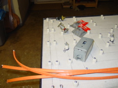
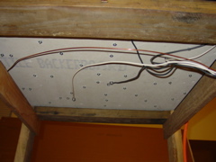
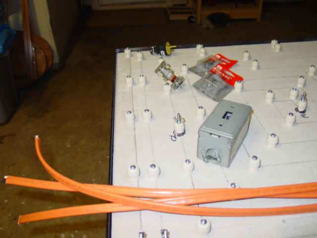
| Now
for the wiring. I started with the high voltage first. Using
10-2G wire, some real big wire nuts, a 20AMP switch, an electrical
box and cover, and a plug, I'm ready to begin. CLICK
HERE for some details. |
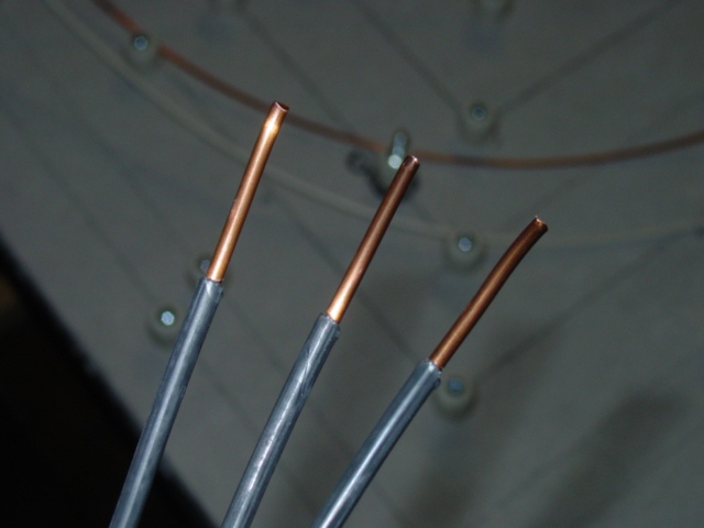
I
cut three, 3 foot segment of wire, and stripped off the orange
outer cover. Then removed the black, white and bare wires.
Then I stripped the ends off the black and white wires like
so These wires will be wrapped around a 2" bolt, so don't
strip too much wire! |
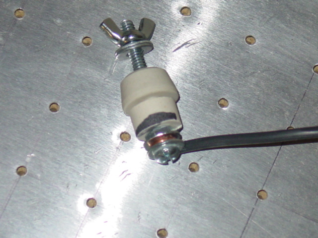
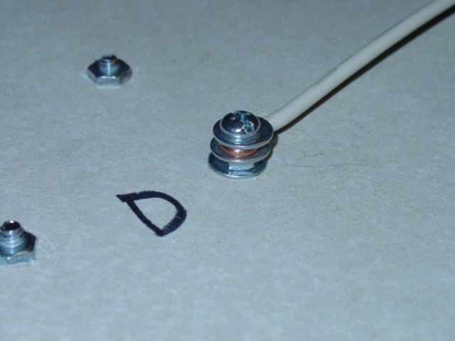
This
is test fitting of my terminal post. Starting from the bottom,
its a 2-inch #10-2 bolt, #10 washer, Wire bent to form around
the bolt, another washer, a #10-24 nut, tightened up, another
washer, the ceramic spacer, two washers on top and finally
a #10-24 wing nut. |
 |
|
|
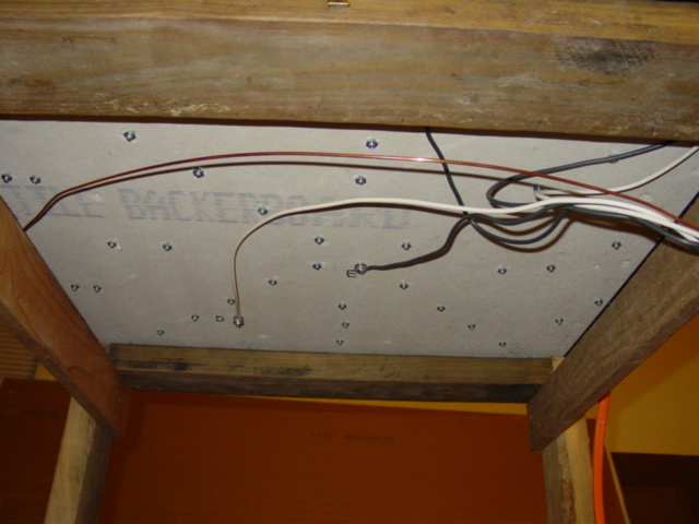
| Here
is an underneath shot of the black and white wires, with the
terminal posts already mounted. There are only 5 to do. Check
the section on this page about oven wiring for details. |
Here
is what the underside of the terminal post looks like. Also,
note the ceramic post mounts, and the distance they stick
out. The 1-1/2" bolts get the job done. |
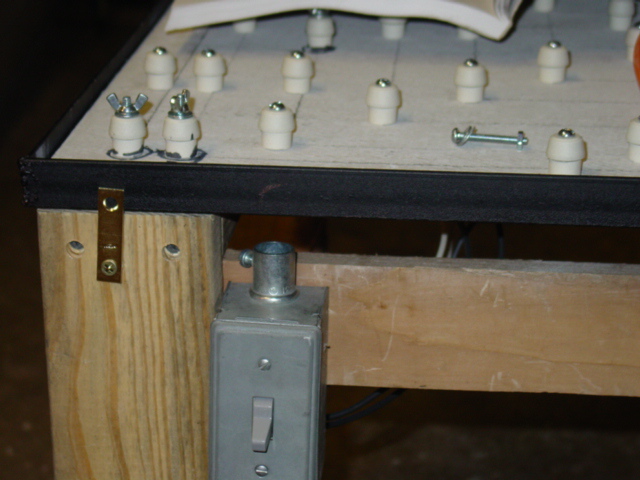
Up
next is the on/off switch, and mounting the switch box. |
 |
|
|
| Wire
pulled to the switch box. All that is left to do is wire these
to the switch, add a power cord, and I'm ready to add the heater
coils. Wiring a light switch basically means take all the black
wires and tie them together with a 4" pigtail using a wire
nut. The wire all the white wires, but this time include the
white wire from the power cord. The switch has the black wires
connected only. The black wire from the power cord, and the
black wire from the pigtail. |
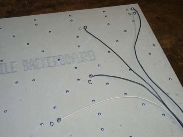
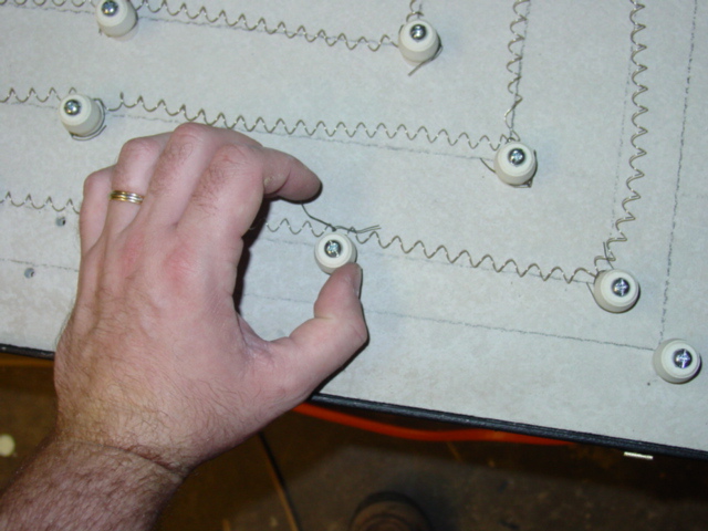
I
got excited and forgot to photograph the wire stretching,
so all I have photo-wise is a shot of the small wires I used
to tie off the heater coils. This process was easy, but my
biggest concern was where to start. The instructions in the
book, call to start from the center of the segment, and start
from post D. The wires have a lot of slack in them, and I'm
not sure if that's good or bad. |
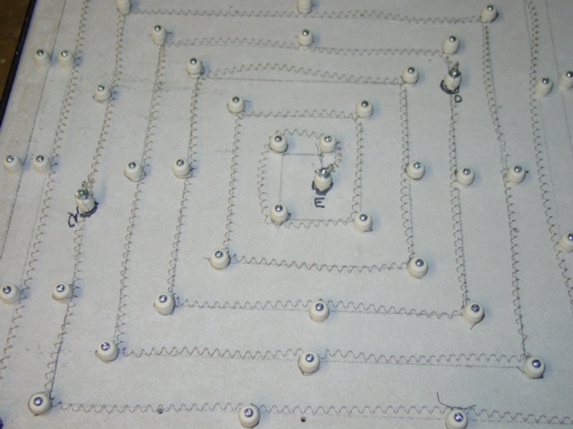
And
the finished oven coils all tied down and ready to test. kind
of saggy coils, but that's ok. After a few test, the last
thing to do is add some head reflectors on the walls to better
control the heat flow. The corners are going to be the cold
spots. |
 |
I
have been asked to take a Ohms reading. Here are the results:
each segment draws about 5 ohms. The resistance varies from
4.9 to 5.1 ohms. I assume this is pretty good considering
the home-made nature of the oven. Total of 20.1 ohms across
the whole oven coil. |
OVEN
WIRE COILS:
From John H. regarding the wire you get from www.infraredheaters.com.
[the precoiled type vs. the instructions found in Thurston
James' book]
"Well,
correct me if I'm wrong, but the book says to wrap the wire
around a 1/4" rod. Infraredheaters.com pre-coiled wire
has an approximate inside diameter of 1/4" so, I think
it's the right size as far as that is concerned.
So basically to calculate how much pre-coiled wire I would
need, I first figured out how many turns per inch the 22
gauge wire gave me by taking the outside diameter subtracting
the inside diameter and dividing that by 2 (.30 - .25)/2
= .025 wire thickness. I then took 1" and divided that
by .025 and got 40 turns per inch.
Then I took 88' converted it into inches (88*12) then divided
it by 40 (26.4) then converted it back into inches (26.4/12)
and came up with 2.2 feet of coiled wire to do the entire
job. If you look at the pic on page 184 it shows the guy
holding 1/2 of the wire required for the entire job and
it looks to be about a foot or so. So I think this calculation
is correct.
With
that said, we should both be able to split the
cost of the 10' precoiled wire and still have plenty left
over. "
And
for the info regarding how much to stretch:
First
I cut a 2' 1/4" [24.25 inches] length from the 5 feet
of coiled wire, then cut it in half to make two 1' 1/8"
[12.125 inches] lengths. I then marked the center of each
length of wire at 6 1/16" with a Sharpie Marker. After
that was done, I put the marked center on a nail, grabbed
both ends and stretched the wire to 95 1/2".
WARNING:
Use a pair of pliers to hold the ends! I made the mistake
of stretching one of the pieces with my bare fingers and
wound up with a nice puncture wound under my finger nail...
ouch!
Thanks
John!
|
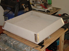
| Here
is the finished oven sans the lid and frame. The next challenge
will be to test the rig without blowing a fuse or breaker! I
also want to try to convert this to a table top machine and
ditch the carts. skill level III, mainly because
the oven parts are hard to get, and the safety concerns regarding
the proper wiring. |
|
|
| The
first test... |
|
|
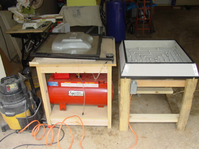
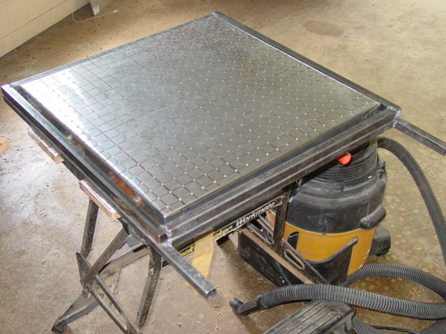
|
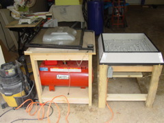
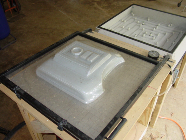
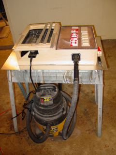
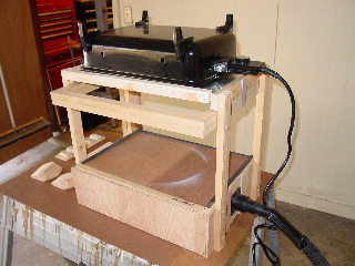
| Here is
my vac-table rig. Note, the shop vac, and the air tank [not
used] Look how much shop space this thing covers.It would be
nice to set the rig on a counter and when its not in use, stack
the oven on the forming surface. |
This
is my first pull using the new table. Some things to note:
the oven takes some time to heat up. I will need to make a
lid for it. And the loose coils might need to be adjusted
to concentrate the heat in the corners. Also, I don't like
the exposed heating elements, so I need to track down some
metal grating material to add as a protector. |
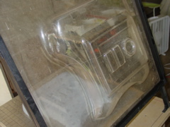
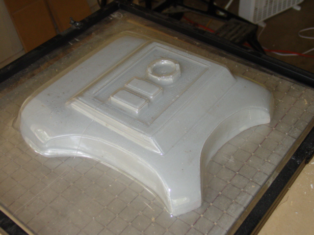
Pretty
decent detail from a sheet of clear acrylic storm window covering!
That stuff was all I had on hand to test with. Its a .125
thick material, and as I expected, the corners did not get
as hot as It needed to. Since my vacuum source was a 3hp Shop-Vac,
I did not expect it to pull as well as it did. |
 |
|
|
| Yes, its
clear, and the beast needs a little fine tuning. The flash s
seemed to exaggerate the dust on the surface, and no, its not
that opaque. Again, the corners need to be reworked, to heater
more evenly, but overall, I'm blown away. |
This
is a shot of the acrylic thickness. Its about 1/8th inch or
.125. Much thicker than I plan to use. |
|
| Making
some test pulls & learning how to use the machine |
 |
|
|
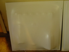
| After getting
some .080 thick HIS sheet and cutting it down to 24x24 inch
squares, I mounted it on the frame, and began trying to melt
it. The oven was not hot enough, and the corners did not get
warm so the pull was poor. No vacuum seal. |
I
continued heating the oven, and installing the lid, I was
able to get a better pull. This one had an issue; there was
such a deep draw between two pieces, the styrene had a hole
pop in between the forearm and the shoulder. This caused a
loss of vacuum and loss of detail. |
So,
I decided to try a wider spacing approach. This seemed to
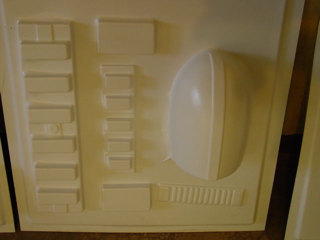
work, and revealed the webbing issues, and the need for risers.
Careful attention to arrangement of the molds on the forming
platen will minimise the webbing issue. |
 |
|
|
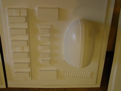
| The oven
had been running for 20 mins. by the time I pulled this, and
I found that if I wear gloves, I can massage the hot plastic
to conform to the mold better. Note, the belt and the shoulder
bell are on risers. The drop boxes, and other small parts are
not. |
I
had one error, I overheated the pastic, and it melted onto
the coils. It was a lost cause. But after reloading the machine,
and using the latest mold, the upper back, I had a good pull.
It too needs a riser to reduce the flare that happens where
the mold sits on the forming surface. |
Here
is a detail shot of the popped plastic. I was really hoping
for a lot of parts that could be pulled at one time with this
machine. I will need to carefully cosider the mold placement
to best minimize these issues. |
 |
|
|
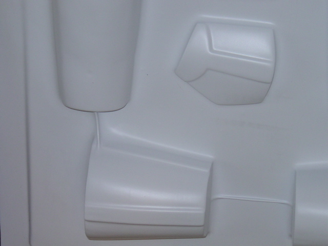
| Take a
look at some of the webbing. Note, that a better arrangement
of the plastic on the forms will reduce the webbing issues. |
Another
detail shot of the last test pull. Pretty decent detail. These
parts are on risers and will trim out nicely. |
A
few more pulls were made over the weekend. I finished the
upper chest and now all the "armor shirt" parts
are done. Time to work on the abdomen and lower back sections.
|
 |
|
|
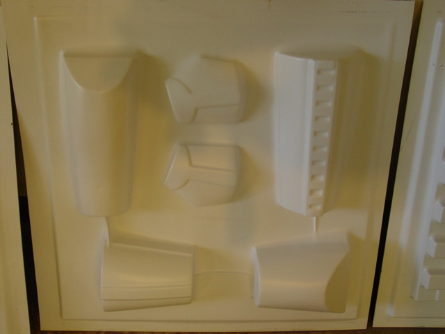
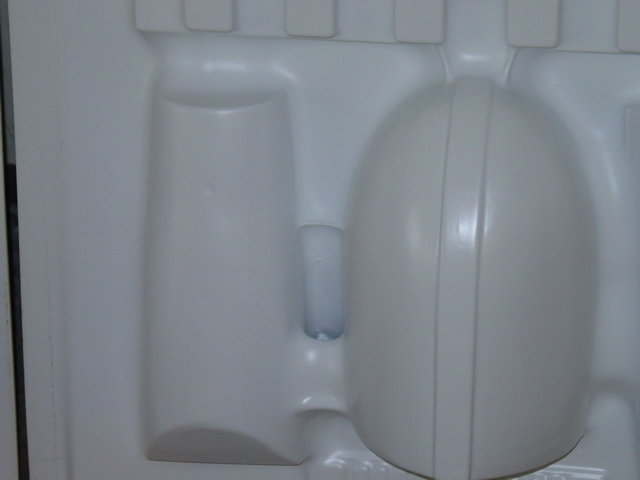
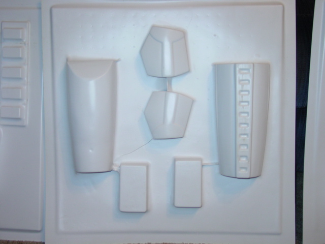
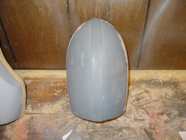
| Each
mold that has a hard deep end to it, like the biceps and the
shoulder bell, are going to need to be reworked with tapers
to aid in the release of the mold from the pulled plastic. |
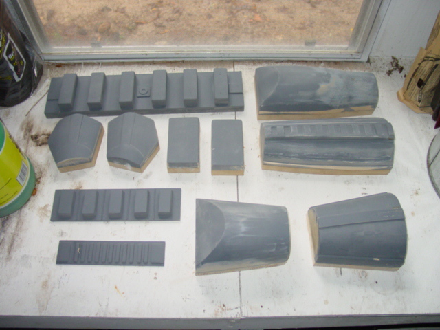
I
am hopefull, if the tapers work, that I will be able to make
some plaster casts from a good pull of the shoulder bell,
biceps and forearms. That way I can pull a complete set in
one pull instead of having to pull the same mold twice. [and
save me from making another mold from scratch!] |
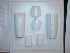
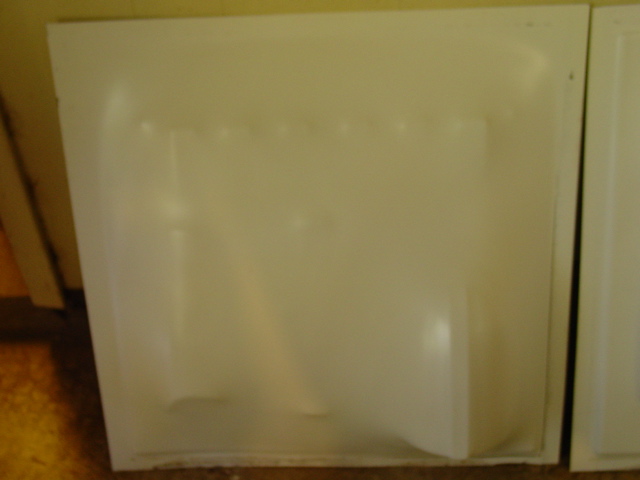
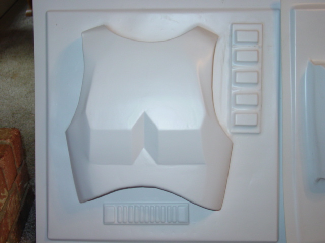
The
collars need to be reworked with an arch built in. The flat
straps just do not bend well. Also, the knee boxes and belt
seem to pull poorly using the thicker .080 material. I need
to use .060 on these parts. Above are some of the molds. |
 |
|
|
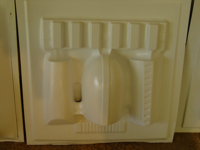
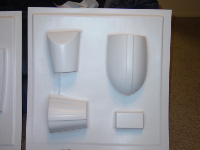
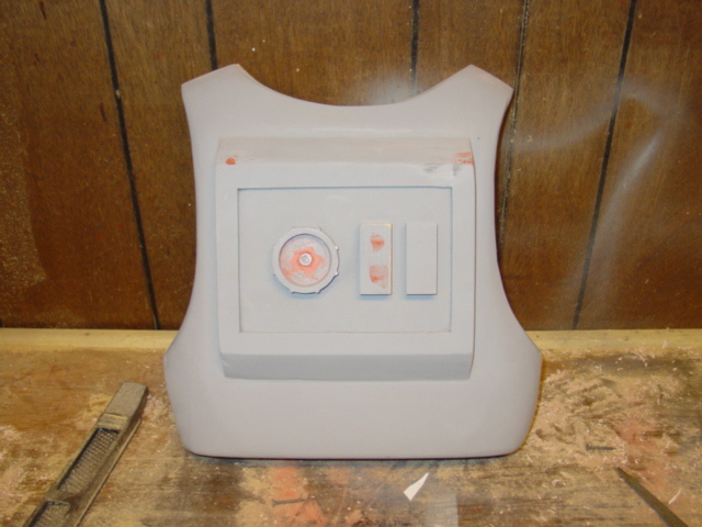
| I'm
pretty happy with the chest mold. It was a challenge to get
the proper shape to the pecks, and I think it worked pout pretty
well. This mold was used before I top coated it with the spot
filler primer. It looks ugly, but it pulls fine. |
As
I make a mold, I learn something new. Bondo is a wonder material!
It helps contour and shape the rough blocks that I make, transforming
them from MDF to vac-molds! A sealer coat also helps hide
imperfections. MDF has a tendancy to fuzz a little on the
surface. It needs a coat of spot putt to smooth things out.
This is th eupper back, and it need some fine tuning, but
its mostly there. |
I'm
working on the scale drawing of the thighs. Once the upper
body is finished, I can see the light at the end of the mold
making tunnel. Once the upper body is made, all that is left
to do are the: inner and outer calves, the inner and outer
right thigh and inner and outer left thigh. Some sort of fabricated
thermal detonator and its off to the helmet molds! |
|
|
Additional
Information
Forming
Surface & Frame
The cost has been a sheet of MDF, and some 3/4" metal tubing.
I had on hand the 2x4's and the casters, hinges, and other materials.
Say $40.00, and if you already have some of this on hand, your ahead
of the game.
Oven
Materials
(Calcium silicate
is expensive!) A temporary working substitute for the oven is James Hardi's
Hardibacker 500*. Available from home improvement centers. Look in
the floor tile or bathroom shower sections of the store. A 3'x 5'
x 1/2" sheet is $10. They are basically a concrete board 60%
calcium silicate. I've talked with a chemical engineer about the
plausible use of this and he seems to think it will work, but I
need to use a 1/2" inch thick sheet instead of the 3/8".
It will get hotter and might not insulate the heat as well. Also,
the engineer suggested lining the interior of the oven with sheet
metal to help support the material. The first test of the oven has
been successful, and the Hardibacker 500 seems to work fine. Including
the angle bracket and screws, the $60 for the ceramic posts, and
another $10 for the NiChrome wire, and factor in another $15 for
the electrical, the cost of the oven is around $95.00.
*It has come to my attention that, over time, the high heat from the nichrome wires will cause the Hardibacker 500 to fatigue, and eventually crack. This could pose a potential fire hazard. Currently a replacement calcium silicate fiberboard is being researched. I got 3 years of regular use from my machine build with the Hardibacker 500, but anyone considering this material should understand it's limits. Consider it a less than ideal substitute.
Vacuum
system
I've given up on the 30gal. tank and Gast 1065 vacuum pump for now.
The proper tank to use is a $144 narrow hot water heater tank from
the home improvement center. For my budget, its just too expensive.
I
did purchased a small
4.3 CFM air-vacuum pump and an el cheap-o vacuum gauge
from Harbor Freight.
Total cost was less than $25. My test pull was done with a 3hp Shop-Vac,
and it seemed to work fine. Cost = $0.00 since I've had the shop-vac
for 10 years!
There are two alternate ways to imporve the vacuum. One will be
to use a second shop-vac. I can use two shop-vacs in sequence and
get more in/Hg instead of the 3-4 in/hg from a single unit. Also,
a check valve might be a good idea, to help hold the vacuum once
it's pulled. I've also purchased a sump pump check valve, that can
be modified to use a spring loaded check valve, and a hi-vac low
volume source. I'm considering my options here. Here is an example
from the book "Do It Yourself Vacuum Forming for the Hobbyiest"
by Douglas E. Walsh.
I've not completely given up on the tank/pump idea, but thats gowning
to have to wait until I can figure a cheap way to plumb it, or I
find a cheap Gast 1023 or 1065 vac pump.
For
the pump/tank vac system, Gast sells different models and the one
Thurston James suggests is Model
1065. Its actually a 8.5 CFM unit that requires a motor.
Gast Model
1023 is a 10 CFM unit with a built in motor. The plumbing
is going to be a nightmare! Here is a list of plumbing gear I need:
- Vacuum
Pump with motor
- Check
valve [so the system dos not back-draw any air through the vacuum
pump]
- air
Filter [so there are not particles to destroy the pump]
- Tank
[30 gallon, 15 is too small; not enough volume]
- Pressure
switch [to keep from imploding the tank]
- Vacuum
gauge [so you can see the amount of vacuum and the vacuum rate]
- Valves
[to close off parts of the system and to open the table valve
to start the pull]
- Plumbing
fittings [lots of these, nipples and elbows, flanges, couplings,etc.]
Conclusion:
Whoa!
It worked! It really worked. I'm just blown away. Why commercial
vacuform/thermoform machines are so expensive is beyond me. The
hardest part by far to make is the oven, and only because of the
exotic nichrome wire and the ceramic posts. If there are hardware
store substitutes for these items, please let me know. Every hobbyist
should make a vacuform machine. If your into model railroad, RC
car and airplanes, scale models, arts and crafts, prop replicas,
costumes, or any other hobby, get to work on your vacuform machine
NOW! Its that easy. Total cost for the test pull: Less than $150.00.
The molds are more work, but once you make a good hearty mold, you
can pull as many copies as you want.
Forming
Supplies:
I
almost gave up looking for polystyrene. Locally, no one seemed to
know what the stuff is. After some research I came to the conclusion
that Polystyrene is a chemical name, High-Impact Styrene Sheets
is what you want to search for. Sometimes called HIPs [High-Impact
Polystyrene Sheet] I've had the best luck searching for HIS [High-Impact
Styrene Sheet] Below are some suggested sources. Be sure to get
48"x96" sheets not the 40"x72" sheets. For trooper
armor you will need between .060 and .080 white. No texture. This
material will have to be gloss coated to get that shiny appearance.
A harder to form material called ABS is used by some to create a
really glossy trooper. Finding that glossy color is difficult. I'm
mainly looking for styrene.
ProfessionalPlastics.com
[good customer service. Thanks Lydia!]
Indplastic.com
USplastic.com
[claims they sell the .080 in 48x96 inch sheets, but I can't find
it in their catalog. Only the smaller 40x72 inch sheets.]
Basic
Math:
Some
basic conversions: .125 is 1/8th inch thick, .062 is 1/16th inch
thick, and .083 is 1/12th inch. .090 is 1/11th.
Ohms:
I
have been asked to take a Ohms reading. Here are the results: each
segment draws about 5 ohms. The resistance varies from 4.9 to 5.1
ohms. I assume this is pretty good considering the home-made nature
of the oven. Total of 20.1 ohms across the whole oven coil.
Misc.
Comments:
Here
are some helpful tips I've received from the RPF and other fine
folks who have helped me out. Thanks guys!
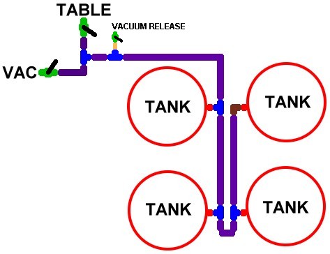
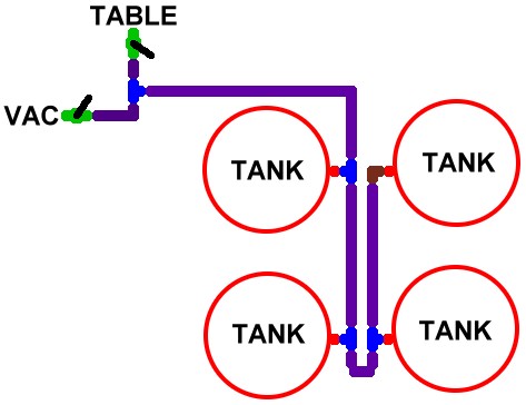
- Click
here or here for
ExoRay's multi-tank vacuum diagram.
- Click
here for John H.'s information
on how to wire the oven.
- Click
here for a gas powered version of
the oven. Thanks Prop_Master Paul!
- Click
here, here,
here and here
for some of Charlie M.'s [TI-386] oven and frame diagrams for
a 24"x32" vacumform machine. Thanks Charlie for sharing
these cool blueprints!
- A
special thanks to Phil G., aka Blaxmyth
for his encouragement, and for getting me off by duff, and to
build a vacuform machine. I just wish I had his mold making
talents. His MDF molds
are great!
Second
pull, and some fine tuning:
Update:
I managed to make several pulls using my new contraption. Here is
what I learned:
- Make
a lid. I used the leftover Hardi-backer 500 material that I
had from the oven construction, and it makes a nice lid. I made
a handle from some angle brackets and a piece of dowel rod and
some large washers. Works great. It speeds the oven heating,
and plastic melt time. But watch out! you can over heat the
plastic! I did! Man, what a mess, and smell!
- I
added a second handle to the frame. This gives extra pressure
to hold the frame to the molds and forming surface. You will
need the extra downward pressure to get a good vac seal.
- The
oven needs time to heat up. You can start pulling hot plastic
in say 5 mins. But the longer time the oven has to heat up,
the better the quality of pull you get. With the oven hot, the
corners even get nice and soft! Thats convection heating working
for you. Don't rush the oven preheat.
- Keep
the lid on at all times. Even when you are heating the plastic.
It sits right on the frame and helps hold the heat in. set it
aside only when you are pulling the hot plastic. Have an assistant
replace the lid on the oven as soon as possible to hold all
that hot air in.
- Wear
leather gloves. When you start to pull a mold, you can massage
the hot plastic to get into the stubborn areas. Also, it keeps
you from burning your hands!
- I
used HIS [High Impact styrene sheet] in a .080 thickness. It
works great, but to be honest, on small parts, you really don't
need that thick of a piece of plastic. It does however work
great for the larger [deeper pulls] pieces.
- The
molds all need risers. Period. Otherwise you get a curved bottom,
and that means poor fitting parts. Also, the molds need to be
fine tuned for easy release from the melted plastic. A slight
taper, grooves, or something to help the parts slip out from
the vac-ed plastic. Each mold had to be pounded out! I even
broke a mold trying to release it. The slightest undercut can
cause this.
- The
imperfections on my molds even show up on the .080 thick material.
I thought it would not be noticable. I was wrong. Time to break
out the Bondo and sanding paper!
- Forming
time is pretty short, say 15 8-10 seconds, with another 5 seconds
that you can massage the plastic with. After that, the plastic
is so still it won't bend anymore. It takes a good 30 seconds
to cool to touch enough to remove the plastic from the frames.
if the molds will release better, the production could go pretty
fast. Right now, I have to pound the molds from the plastic.
- Overall
I pulled seven panels in about one hour. 2 were good enough
to give away to a friend who wanted the parts, one was a boo-boo,
total melt-down, and one was not hot enough to form. One was
OK and I trimmed out the parts, and one was decent, but not
good enough to use any of the parts. It does make an interesting
wall art decoration though!
What's
next:
- Take
oven thermometer and check the temperature. It gets plenty hot,
I'm just curious how hot it gets.
- Add
a metal grating above the coils to hopefully keep the overmelted
plastic from ruining my heater coils.
- Rework
the vac system. The 3 HP shop-vac is ok, but a better option
might be a combination of technologies, a cut-off valve, and
a low volume, high vacuum secondary system for stronger pulls.
Click here for a diagram.
UPDATE
10-15-09
It has come to my attention that, over time, the high heat from the nichrome wires will cause the Hardibacker 500 to fatigue, and eventually crack. This could pose a potential fire hazard. Currently a replacement calcium silicate fiberboard is being researched. I got 3 years of regular use from my machine build with the Hardibacker 500, but anyone considering this material should understand it's limits. Consider it a less than ideal substitute.
UPDATE
6-25-05
I've
been running the machine for some time, and have pulled a total
of 9 suits. [one suit averages 16 trips through the machine, for
a total of 144 pulls] Some things I have learned; the Hardibacker
500 will crack after prolonged use. Not sure why, or how bad it
will get, but I intend to keep using it until the oven falls apart.
Another option would be to make a box for the frame, and line the
box with insulation material and shield it with aluminum. I'll do
that when the oven falls apart, but until then I'll keep using the
current system.
The
3M non-skid material I was using for the holding frame to 'grip'
the plastic, has started to come unglued. I lost several pulls
due
to this, so I reworked the holding frame's grip material this time
using JB-Weld, and play sand. I mixed the JBWeld, a 2 part engine
epoxy according to the instructions, and smeared it on the inside
of the holding frames where the 3M material was.Then sprinkled
it
with a good dose of play sand that I had sifted to remove the really
big pieces. Then let it dry over night. The results appear good,
and the JB weld is suppose to resist temps up to 300 degrees
C!
That is way more than I'll need. Also, I can always add more JB-Weld
to the frames if I need to.
Also,
I have upgraded the vacuum system to use a 6.5 HP shop vac and my
old 3.0HP shop vac as a booster. To be honest, I really can't tell
much differece between the pulls the 6.5 make vs. the 3.0. I was
hoping for a big boost, but thats just not the case. I've tried
running them in parallel, and can on occassion get a tighter pull,
but this is not consistent. I need to add the cut-off valve, and
a high vac secondary system.
Finally,
I tried some .062 ABS. One side glossy, the other side a 'haircell'
texture. With my current oven setup it heats fine. No orange peel
or other heat issues. My problem pulling ABS is with the vacuum
side. The ABS has more rubber in it, and it is much slower to cool
down compared to HIPs. My vacuum system can't seem to stay up with
the needed vacuum to hold the shape before the plastic cools back
off. For now, I will stick with HIPs.
I've
added a discussion
board for questions and feedback from other vac-formers.
Check it out!
You
can help support this site by purchasing a book version, with additional
how-to information. Just click on the button below:

Older News
[Update 28-January-2007]
Just
a short update:
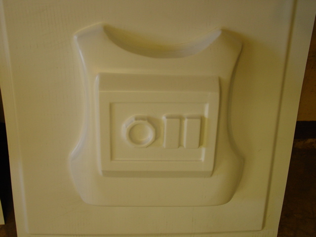
- The new holding
frame clamps on the vacuum form machine worked great. Here is
a peek at the new clamps:
The
History of my Vacuum form Machines
Follow
along as I tried to make a practical vac-table on a shoe-string
budget.
| |
Vacuform
machine #1 prototype
This is
the Mark I desing based ona website I found. Simple and quick
to construct but had some issues. Mostly heat relate. Click
here for more info on this design. |
| |
Vacuform
machine #2
The Mark
II used parts from the original Mark I but incorporated an
Over/under design. Worked much better but still had some heating
problems. Click here to learn
more about this design. |
| |
Vacuform
machine #3
The Mark
III "oven scale" design is much improved but again,
still plagued with heat and a size forming table large enough
to accomidate the larger Stormtrooper armor. Click here
form more info. |
|
Vacuform
machine #4 Thurston James type
T he final
table design, based on Thurston James' design from his book.
This has a 24"by 24" holding frame, and will use
a vacuum pump/vacuum tank for the vacuum process. Also, a
custom made 28" by 28" electric heating oven will
be made. Click here for more
information. |
Supplies:
Below
is a running list of parts and materials I used to make the vacuum
forming machine.
| BASIC SUPPLIES |
| QTY. |
Name |
Size |
Source |
| 1
Sheet |
MDF
[Medium Density Fiberboard] |
3/4"
by 4' by 8' |
Lowes
or Home Depot |
| 3
tubes |
square
metal tubing |
3/4"
by 3/4" by 6' |
Lowes
or Home Depot |
| 6 |
#2
2x4 pine or fir |
stud
length |
Lowes
or Home Depot |
| 1 |
3/4"
Floor flange or 1" floor flange |
3/4"
or 1" |
Lowes
or Home Depot |
| 1
sheet |
Sheet
metal [aluminum] |
24"
by 24" |
Lowes
or Home Depot |
| 1
tube |
silicone
caulk |
|
Lowes
or Home Depot |
| 2 |
piano hinge hardware |
3/4"
x 4" |
Lowes
or Home Depot |
| 2 |
bolts
for clamping hardware |
|
Lowes
or Home Depot |
| 2 |
wingnuts |
|
Lowes
or Home Depot |
| 1 |
dowel
rod |
3/8"
dia.by 5" |
Lowes
or Home Depot |
| 1
sheet |
Hardibacker
500 backer board ** |
1/2"
x3'x5' |
Lowes
or Hoime Depot |
| 1
roll |
nichrome
wire |
#22,
81 Feet |
Infraredheaters.com |
| 56 |
ceramic
posts |
item
# PI-B-1-S |
Infraredheaters.com |
| 1 |
Vacuum
Pump 10 CFM Gast model 1065, 1022 or substitute * |
10 CFM |
Gast,
Ebay |
| 3 |
3/4"
ball type valves * |
3/4"
threaded |
Lowes
or Home Depot |
| 1 |
hot water
tank, pressure tanks, air tank or propane tank * |
30 gallon
"slim" hot water heater |
junkyard,
RV center, Lowes, or Home depot. |
| 1-2 |
3hp
or better Shop-Vac |
3hp
or better |
Lowes
or Home Depot |
| 1 |
Sump
Pump check valve |
1-1/4
to 3/4" |
Lowes
or Home Depot |
| 1 |
10-2-G
electrical wire |
25' |
Lowes
or Home Depot |
| 1 |
20am
light switch [gray] |
20amp with ground |
Lowes
or Home Depot |
| 2 |
large
wire nuts |
#10
- 4 wires |
Lowes
or Home Depot |
| 1 |
Light
switch box with cover |
std |
Lowes
or Home Depot |
| 1 |
3
prong electrical plug with ground |
20amp |
Lowes
or Home Depot |
| 1
box |
1-1/2
inch screws with nuts [50] |
#10-24 |
Lowes
or Home Depot |
| 1
bag |
2
inch screws [5] |
#10-24 |
Lowes
or Home Depot |
| 1
bag |
flat
washers [25] |
#10 |
Lowes
or Home Depot |
| 1
bag |
wing
nuts |
#10 |
Lowes
or Home Depot |
| |
* not used so far in this project
**It has come to my attention that, over time, the high heat from the nichrome wires will cause the Hardibacker 500 to fatigue, and eventually crack. This could pose a potential fire hazard. Currently an replacement calcium silicate fiberboard is being researched. I got 3 years of regular use from my machine build with the Hardibacker 500, but anyone considering this material should understand it's limits. Consider it a less than ideal substitute. |
|
|
|
| This
project was last update on October 15, 2009. |
|


